Everything becomes a cloud
Table of Contents

Hello Everyone,
Today, I’d like to share with you some thoughts on a complex topic : The evolution of computer networks and what drives this evolution.
How did we transition from the traditional 3-tier architecture of our data centers (access, aggregation, core) to the Clos architecture (Leaf-Spine “Clos” architecture) we know so well today?
Some might say it’s simply a technical evolution driven by protocol limitations and/or cost considerations.
Others, like myself, believe it goes beyond that and involves factors such as marketplace and government regulations.
Introduction#
As a reminder, the stakeholders in computer networks are :
- Network equipment vendors (e.g., Cisco, Juniper),
- Application developers (e.g., Facebook, Google, Amazon, Microsoft),
- Network operators (e.g., AT&T, NTT),
- End users (individuals or enterprises).
In a perfectly ideal world, everyone sticks to their roles. However, large providers (Amazon, Microsoft and Google), have started spreading their wings. They’ve ventured into building their own network equipment (check !) and even deploying and managing their own networks (check again!). Finally, as expected, they continue delivering services and applications to their users on top of their own networks. They are playing multiple roles.
Let’s see how all this came together to give the networks we know today.
1. Legacy DC Architectures#
The figure below shows the network design that dominated in the early 2000’s.
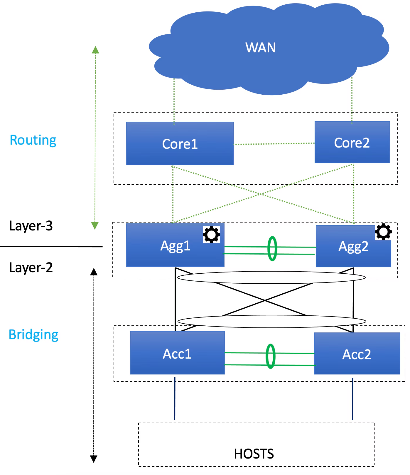
When it comes to traditional network architectures, endpoints typically connect to access switches, forming the foundational layer of the network. These access switches are connected to aggregation/distribution switches, which then connect to the core network.
Why two aggregation switches? Back in the day, having a pair seemed like a solid plan for redundancy and throughput. If one failed, the network could still function. For a while, this setup worked well enough. But the redundancy was no longer enough, and throughput bottlenecks became more frequent.
Another key detail: the way traffic flows between these layers. Between the access and aggregation switches, traffic moves using Layer 2 (L2) networking, also known as bridging. Beyond the aggregation switches, however, the network shifts to Layer 3 (L3) networking, or routing.
This classic architecture served its purpose well for years.
Here is some limitations of this architecture :
- MAC Address Table Size: Limited table size causes inefficiencies like packet flooding in large, virtualized networks.
- VLAN Limits: The 4094 VLAN cap becomes insufficient in multi-tenant environments, complicating resource sharing.
- STP Bandwidth Inefficiency: Spanning Tree Protocol blocks redundant links, halving potential bandwidth and impacting performance.
These issues highlight the limitations of legacy architectures in meeting modern data center demands.
2. Clos Network Architectures#
This is the most common Clos topology also called leaf-spine topology :
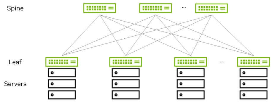
Originally developed by Charles Clos 1953 for telephone networks, the Clos topology uses multiple smaller, low-cost switches instead of relying on a few high-capacity devices. This approach distributes traffic and ensures better fault tolerance, scalability, and redundancy. The architecture typically consists of 2 layers:
- Spine Layer: Provides the core interconnect.
- Leaf Layer: Connects directly to servers and storage.
The spines do not provide any other service, in contrast to the aggregation switches in legacy data center architectures, although they structurally occupy the same position.
In a Clos topology, all functionality is pushed to the edges of the network, the leaves and the servers themselves, rather than being provided by the center, represented by the spines.
The Spanning Tree Protocol (STP) is not used, instead we use Equal-Cost Multipath (ECMP) routing to forwarded a packet along any of the available equal-cost paths.
Dimensioning Clos Architectures#
The main reason for using higher-speed uplinks is that you can use fewer spine switches to support the same oversubscription ratio. For example, with 40 servers connected at 10GbE, the use of 40GbE uplinks requires only 10 spines, whereas using 10GbE uplinks would require 40 spines.
3. Why the Shift from Legacy Architectures?#
Traditional tree-based designs suffered from over-subscription, limited bandwidth, and inefficient redundancy mechanisms. Clos networks address these pain points with:
- Non-blocking bandwidth: Better handling of east-west traffic (common with modern workloads like microservices).
- Scalability: Easily accommodates growing workloads by adding switches horizontally.
- Cost efficiency: Uses smaller, commodity switches rather than expensive, high-speed monoliths.
What if I told you that the Clos architecture has always been present in our designs, even in the 3-tier architecture?
Here is an inside view of a Cisco Nexus 7000 modular switch that has been used as a core/distribution switch for decades in traditional 3-tier networks :
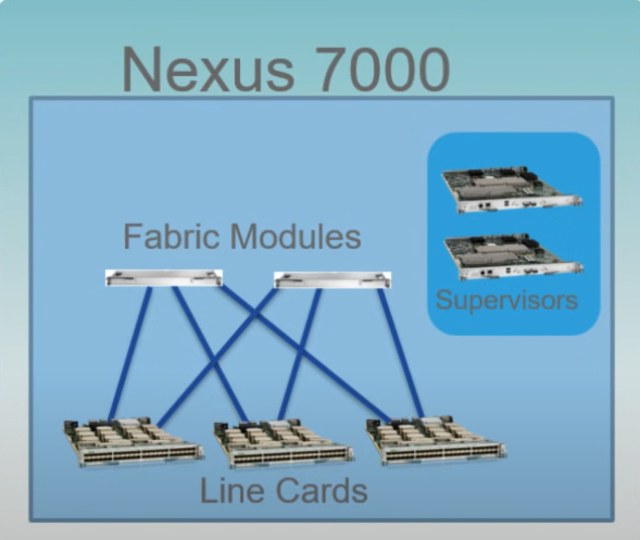
The architecture shows how fabric modules interconnect line cards (network interface cards) with the supervisors playing the role of the brain managing the entire chassis in modular system. It’s just a Clos architecture inside a modular chassis.
Below is a view of a typical design, as we have seen many hundred thousands of times, featuring two sites connected by Cisco Nexus 7000 modular switches (I’ll let you imagine the rest of the access equipment : Nexus 5000 and nexus 2000 switches):
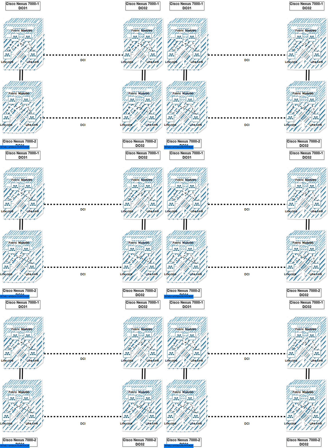
Ok, this is where things get a bit technical. At the time, building large-scale Layer 2 (L2) networks became increasingly popular, driven in part by the need for virtual machine mobility (e.g., VMware’s vMotion).
The major design challenge was: how do we enable live migrations of VMs between data centers that are not in the same L2 network?
One solution to this problem (before VXLAN) was Cisco’s OTV.
OTV introduces the concept of “MAC routing,” which means a control plane protocol is used to exchange MAC reachability information between network devices providing LAN extension functionality (It’s a fancy GRE tunnel).
This is exactly what VXLAN was designed to do but with more features compared to Cisco OTV :
- Scale beyond 4k Segments (VLAN ID Limitation)
- Efficient use of bandwidth (Blocked/Unused Links/ STP)
- Leverages ECMP (Path Optimization)
- Can rely on EVPN MP-BGP as control-plane.
4. Networking has become a software business#
We all know that large cloud providers (practically demi-gods these days!) excel at developing software on top of commodity hardware. They have mastered the art of the DevOps model, breaking down barriers between development and operations.
Here is a view of a modern multi-site fabric based on Cisco Nexus 9000 switches :
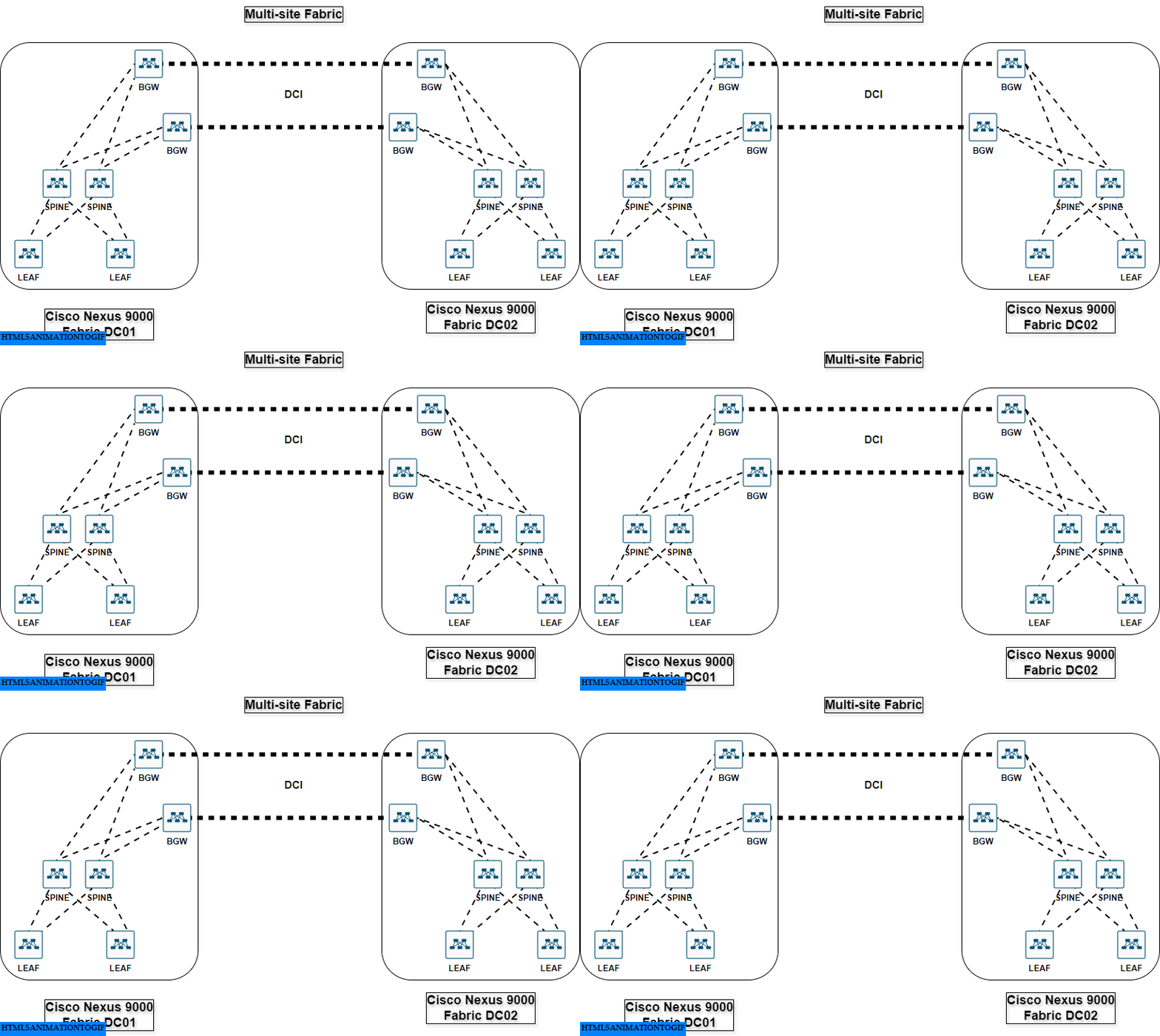
This fabric is generally provisioned by solutions like ACI or NDFC, this is basically the equivalent of the supervisors in the Cisco Nexus 7000 chassis, defining how to route traffic between leaves. The key difference is that it rely on standard protocols like VXLAN & EVPN MP-BGP to emulate a big modular switch or more.
This major transformation, known as Software Defined Networks (SDN), was driven by large cloud providers. This transformation is referred to as the “cloudification” or “softwarization” of the network.
Conclusion#
This perspective raises many questions. The first is about the future of network equipment vendors in this evolving landscape. The second, more political and directly relevant to us :
Are we ready to give full control to cloud providers to shape not only the future of computer networks but also the future of the internet itself?
And you, what do you think of the growing monopoly of cloud providers?
Let me know what you think about this series, and stay tuned for the next post!
I hope you found this informative. If you have any comments, feel free to let me know by sending an email to: nazim@amfdigitalroute.com.